The Automotive Future is Electric – Unlock Success with the Right Concepts and the Right Partner
Since the invention of the automobile and the emergence of the automotive industry behind it, change has been a constant driving power. The rate of change has sped up considerably in recent years – one reason being due to political causes – with analog fossil-fuel-based vehicles making room for highly connected, emission-free electric vehicles (EVs).
The automotive industry is meeting this change with high-innovation efforts in the technical-digital and mechatronic segments. At the same time, end consumer’s influence on automotive development during the last decade has increased so far that it has become both an origin point for automation innovation as well as a core defining factor for its success – or failure (Diez, 2017, p. 55-57).
Core topics of e-mobility revolve around driving range and charging infrastructure. One decisive and often underestimated factor for optimizing both charging speed and effective driving range is the vehicle’s thermal management. For example: By purposefully preconditioning the EV battery, charging cycles can be made more efficient.
Electric vehicles are defined by a variety of characteristics and must therefore be developed convincingly as a whole. This means that in addition to the previously described central topics of e-mobility, the requirements for electric vehicles regarding drivability, safety, and driving dynamics must be at least match those of internal combustion engines (ICEs). For those characteristics of complete vehicle development, the placement, protection, and validation of the high-voltage battery are of central importance.
In this article, we outline how Magna can support your commitment to EV’s via comprehensive development expertise in all relevant areas:
> Many Roads Lead to Driving Range – Energy Management in EVs
> Breaking a sweat while fast charging? – Challenges of thermal management in BEVs
> EV Charging Technology as Key Factor for Positive User Experience
> Vehicle Control Unit – The Mastermind Behind All Vehicle Functions
> Over 1000 V in the future? Integration of HV battery and drivetrain in the electric car
> Battery Development for High Voltage Battery Electric Vehicles – A Supercharged Subject
MANY ROADS LEAD TO DRIVING RANGE – ENERGY MANAGEMENT IN EVs
In EV development, improving individual automotive systems and aspects in isolation is insufficient. Without a holistic view, it will not be possible to achieve a comprehensive optimum.
One of the primary goals of developing a battery electric vehicle (BEV) is maximizing the vehicle’s driving range via optimal energy management. It is mostly determined by a combination of efficiency and battery size. However, implementing a bigger battery with greater energy reserves does improve driving range, but it also increases the overall weight of the vehicle, and therefore actually decreases efficiency. However, efficiency is an important criterion for the end customer because it determines the cost of each kilometer driven in vehicle operation.
The development team’s aim is not only to maximize the nominal range under the normal and favorable conditions of WLTP testing, but also improving the real driving range and cost factors which are relevant for the customers. High customer satisfaction can only be ensured long-term if a vehicle shows good performance in these factors, within a close range of WLTP test scores. And that is, of course, of central interest to vehicle manufacturers.
Compared to internal combustion engine vehicles (ICE) with its multi-step transmission, electric vehicles come with significantly fewer adjusting screws within the powertrain itself to minimize real energy consumption and thus optimize driving range. Therefore, factors that influence the complete vehicle are of particular importance here. These factors include, among others, aerodynamics, reducing friction losses, and minimizing rolling resistance.
A HOLISTIC CONSIDERATION OF THE COMPLETE VEHICLE
Even if the same type of battery and power train are used, there is a significant difference in energy consumption and driving range depending on the vehicle’s basic concept and design. For example, SUVs are designed for greater spatial proportions, better aptitude for rough terrain, and powerful tractive output for pulling trailers. Of course, these use cases do not allow much leeway for energy efficiency. Hence, an SUV will never range the same efficiency levels as an aerodynamically advantageous, minimal weight vehicle optimized for high driving range.
Nonetheless, even the energy management of a vehicle with high consumption can be improved by optimizing elements of all divisions. One such approach to improve driving range is the efficient construction of the engine. In the next step, frictional resistance is minimized in the remaining power train. Then, tractive resistance (which consists of aerodynamics, rolling resistance, and complete vehicle weight) is reduced as much as possible. Thermal management also plays an important role in increasing the efficiency and therefore, the driving range of a battery electric vehicle (BEV) because unlike with ICE vehicles, energy for heating must also be borrowed from the battery.
A DRIVE FORMULA, TAILORED TO THE DESTINATION – ALL-WHEEL DRIVE CAN BE EFFICIENT
A power train’s basic concept must be suited to the needs of the intended target customer group. Hence, it should be designed in a way that solves target conflicts regarding the different customer’s expectations of the vehicle. One customer group might prefer good driving performance while another group is focused more on energy efficiency. A modular power train building block system offers a great solution for this problem. With this modular system, it is easily possible to build a version of a vehicle with one powered axle and another version of the same vehicle with two powered axles. While the vehicle with one powered axle can be offered as an entry level model build for driving range, the all-wheel drive vehicle acts as an alternative with higher overall performance. Moreover, the all-wheel drive feature provides an attractive additional selling point for any battery electric vehicle. The active torque distribution between the two drive axles presents another possibility to positively influence driving dynamics.
Optimizing power train design
On the surface, an electrified all-wheel drive has certain disadvantages conditioned by principle, like how two powered axles can increase overall weight and decrease available space within the vehicle’s design. However, higher performance potentials also enable better output levels in BEVs, since they perform better in partial load scenarios than internal combustion engine vehicles. This is already in use today with serialized vehicles. Also, even vehicles with one powered axle are usually outfitted with an overdesigned engine since the real use of BEVs incurs fewer high loads. This is especially important for constant driving as this use case is the most common type of normal driving operation.
There are more advantages to harness from all-wheel drives by decoupling one axle, for example the secondary axle, during phases of constant driving. This proves especially effective in combination with complementary rating of the primary and secondary drives.
Here, the rating of the drives occurs in a way that the efficiency sweet spots lie in different velocity ranges, which makes them complementary to each other. This way, two drives can create a far broader efficiency sweet spot through the complementary usage than only one drive ever could, resulting in a simultaneous increase of performance potential.
These advantages are of particular use to vehicle segments that need high performance anyway due to high driving range and consequently, heavier batteries. Usually, this also coincidently overlaps with vehicle use cases which are defined by higher customer expectations of traction and drive dynamics. Hence, it depends on the individual use case which solution makes more sense. However, contrary to ICE vehicles, an electric all-wheel drive can actually prove more economical.
CONVERGING NOMINAL RANGE AND REAL DRIVING RANGE
How much the WLTP nominal range and the real driving range of a BEV deviate from one another heavily depends upon usage profile: How similar is the expected vehicle usage to the standardized measurement methods according to the WLTP driven run? Generally, nominal range can be useful information for the end customer to objectively compare different vehicles. However, standardized measurements can never accurately reproduce the real vehicle usage of a specific end customer since nominal range is determined by a fixed run simulating urban traffic, rural traffic and highway traffic. That is why there can inevitably be higher values if the real usage varies from this particular route type allocation. For example, driving primarily on the highway will increase energy consumption and shorten the driving range. Thus, the aim of holistic energy management is to converge these two values in the development phase already.
The way this is achieved varies greatly depending on the vehicle’s concept and must be specified in the cooperation between OEM and development partner. On one hand, aerodynamics and the tires’ rolling resistance are much more important for vehicles meant for frequent long-distance travelling at higher velocity. On the other hand, a battery electric vehicle meant primarily for urban short-distance traffic with frequent deceleration, stagnancy, and subsequent run-ups must be optimized in terms of minimizing overall weight, maximizing the recuperation of braking energy, and optimizing energy demand for the vehicle’s A/C.
ARE TIRES PART OF ENERGY MANAGEMENT?
Minimizing tractive resistance as a central element of energy management determines the choice and design of individual vehicle components. Tires play a key role in that matter. On one hand, wheels and tires are an important design element and must match the vehicle’s overall style. On the other hand, they also heavily influence tractive resistance. This not only applies to rolling resistance itself, but also to air resistance and weight. A tire that bears on a small surface area and barely churns minimizes not only rolling resistance, but also decreases air resistance due to its low width. However, a tire with relatively hard rollover reduces driving comfort and negatively influences driving dynamics. Therefore, a higher effort must be made while developing the chassis and modulating control systems for driving dynamics to ensure an acceptable comfort experience and safe driving behavior of the vehicle. Depending on the OEM’s requirements, tradeoffs in one area are necessary in order to optimize another area.
That is why OEMs can profit greatly from a development partner like Magna since they not only provide decades-long experience in all areas of vehicle development and adjusting components, but can also validate the systems’ performance and robustness in on-location test sites and test rigs.
THERMAL MANAGEMENT AS AN IMPORTANT ELEMENT OF ANY ENERGY STRATEGY
The design and adjustment of the thermal system plays a particularly important role in the energy management of battery electric vehicles. Since the WLTP measurements of the nominal range are run in 23°C environmental temperature and without climatization, there is no consideration for energy consumption due to the climatization of the vehicle and the electric batteries. However, this aspect can have a great impact on the real driving range since the thermal system influences both climatization and performance potential while charging and driving. On one hand, the higher energy demand due to heating the passenger cabin during cold environmental temperatures increases energy consumption and battery strain, and negatively impacts the energy balance. On the other hand, efficient battery cooling can greatly benefit fast-charging capabilities and the high-performance aptitude of the power train.
However, even in this area, compromises are necessary and must be made according to the requirements of the individual vehicle project which the OEM and development expert have defined together. Involving the development partner in an early stage of the project can not only shorten the overall development duration, but also decrease development costs since challenges and design problems can be avoided on time.
DRIVER COACHING AS A CHANCE TO IMPROVE REAL EFFICIENCY
Even when the vehicle’s systems provide all requirements for optimal energy management and maximum efficiency, the individual driver can experience a real driving range that undercuts the WLTP measured nominal range. This can happen when a battery electric vehicle is willfully or unknowingly operated by the driver in an energy-adverse fashion. This is where the so-called driver coaching via the vehicle’s infotainment systems can make a difference and exceed pure entertainment and information service in the near future. It can provide the drivers with guidance about operating the vehicle with utmost energy efficiency, by offering different driving modes like energy saving mode, normal mode or performance mode, for example.
The driver coaching will be adapted according to the chosen driving mode – for example, it can be assumed that the driver is knowingly forfeiting maximum driving range when choosing performance mode, so there will be no or less guidance from the system. On the contrary, guidance will be offered when drivers choose the energy saving mode, efficiency mode or economy mode to ensure actual optimal energy savings and maximum driving range. It can be assumed that the driver is not excepting a high-velocity driving experience while choosing these modes.
Route planning and driving habits as factors of energy management
Interconnectivity with the navigation system and observation of frequent driving habits offer further possibilities to increase real efficiency. For example, if the system detects a commuting habit of operating the vehicle for a short distance for the duration of ten minutes each morning, it may hint that the complete vehicle does not need to be fully heated up or cooled down to optimal operating temperatures, thus saving energy. In contrast, climatizing the passenger cabin and the batteries to optimal temperature makes sense if the goal of the route navigation is 300 kilometers away, since a battery in optimal operating conditions can provide more energy and improve fast-charging capabilities if necessary. Interconnectivity with route navigation and information can also improve efficiency in some cases. For example, it could determine if it is better to use the vehicle’s momentum or to increase recuperation strength for a purposeful deceleration.
In this aspect too, Magna as a development partner can act as an intersection between subsystem suppliers to ensure that the driver coaching can provide guidance for actual utmost efficiency. To provide another example, it can be more energy efficient to concentrate the passenger cabin climatization on only one seat if the vehicle is operated only by one person instead of opening the window or roof-light since this measure can decrease aerodynamics and negatively impact efficiency more than the usage of the A/C.
No exhaust gas clearing system, no multi-step gearbox: EVs are quite different from conventional ICEs in several areas, and often appear less complex than them as a result. However, thermal dynamics are the opposite: The need to integrate several additional functions and its expanded range of functions beyond passenger amenities make the BEV’s thermal system considerably more sophisticated than that of ICE variants.
BREAKING A SWEAT WHILE FAST CHARGING? – CHALLENGES OF THERMAL MANAGEMENT IN BEVs
The thermal management of a battery electric vehicle (BEV) directly influences its mileage, its charging duration, and its operational strategy. In a combustion car, the lost heat of the engine is diverted to the environment via exhaust and cooler, or it can be reused to heat the passenger cabin. Usually, the cooling energy for the cabin’s A/C is generated in an entirely separate refrigeration circuit.
In an electric vehicle however, the thermal system becomes an integral part of the vehicle’s complete system. This is because the lost heat generated by the high voltage battery cannot be directly diverted through the environmental air alone. Since its target temperature can be below the environmental temperature, the high voltage battery must be further cooled down via the refrigeration circuit.
So, on one hand thermal management systems of BEVs must be more effective overall. And on the other hand, heating and cooling the passenger cabin becomes more complex than in combustion cars. Arising challenges and their solutions will be discussed in this article.
Table of Contents:
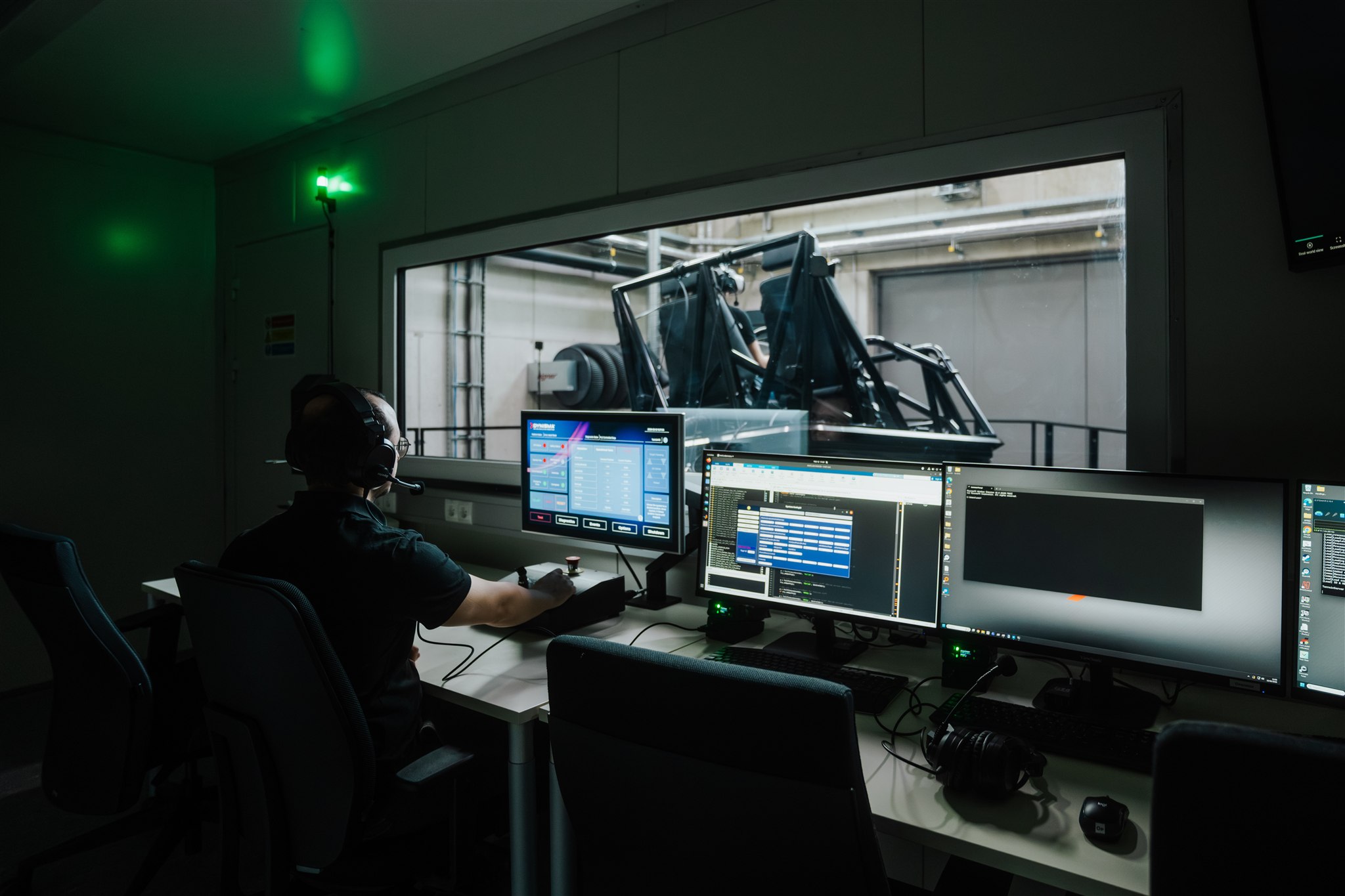
- Development and Validation – in Simulation and on the test rig
- Fast charging as the greatest challenge of thermal management
- Heating a BEV – Will all future cars have a heat pump?
- Expedient conception prevents the need for re-development later
DEVELOPMENT AND VALIDATION – IN SIMULATION AND ON THE TEST RIG
Generally, when designing a new vehicle, the thermal system development should not start later than the concept phase. As soon as the vehicle’s basic architecture, design and performance requirements are defined, the conceptualization of the thermal system can begin. After that, the development is carried out in three stages, with the physical testing of the actual vehicle occurring in the last stage.
The simulation phase offers the most freedom to determine relevant parameters across the whole thermal management system. On the system test rig, the thermal system’s performance as well as its long-term stability is validated. For example, the robustness of oil flow in the refrigeration circuit. The compressor needs oil for lubrication, which circulates together with the cooling agent. But the more complex the system and the longer the lines, the more oil will accumulate and settle throughout the system – and will then be missing from the compressor.
Consequently, it is of utmost importance to identify potential challenges beforehand so the system can interfere in time in case of danger, even from the software side.
Expertise and the right equipment make all the difference
Magna can provide new entrants into the BEV market with everything they need to develop a new vehicle. Established OEMs have the goal of using available system concepts from already serially produced vehicles, even for new models.
However, an already existing system cannot be fully integrated into a different vehicle, and many components must be re-constructed and re-developed from scratch. This can be the case if vehicle requirements change or if the vehicle’s installation space makes it necessary to rearrange components due to the car’s design. Even changing the conduits may require redoing preliminary validation of the overall system to prevent problems during the installation process.
For this reason, Magna has developed an intricate system test rig with two independent, but couplable climate chambers for comprehensive validation. The rig can reproduce any imaginable scenario of thermal management, even especially challenging constellations of high environmental temperature, a cabin with intense need for cooling and active fast charging at the same time.
FAST CHARGING AS THE GREATEST CHALLENGE OF THERMAL MANAGEMENT
When constructing the thermal system, the combination of fast charging the traction battery and maintaining the driver’s cabin comfort poses the greatest challenge. This is because the battery generates a large amount of heat that needs to be diverted when fast charging. At the same time, it is in the passenger’s interest to keep the cabin nicely climatized.
Therefore, compromises need to be made. An enormous cooling system would be required to keep the battery at optimal operating temperature while fast charging, especially during high environmental temperatures and while simultaneously cooling the cabin. Depending on the manufacturer’s requirements, the middle ground needs to be found or a decision needs to be made: Should charging times be extended or does the passenger compromise for less comfort?
Of course, the vehicle’s target group focus plays a major role in these types of decisions. A comfortable upper-class vehicle cannot compromise on cabin comfort as much as an inexpensive car can.
Higher power output does not have to come with lower efficiency
Another challenge for the thermal management system is the combination of a higher demand for power output with a lower target temperature inside the driver’s cabin. Usually, the cabin is cooled down by inlet air between 2°C and 10°C, which causes low pressure and hence, low density in the cooling agent.
This decreases its efficiency and means that the cooling agent compressor has to have greater dimensions or be able to spin much faster. The battery cooling requires higher target temperatures, and due to the suction pressure, the system can work more efficiently and perform better.
In principle, the regulation in EVs is facilitated by electrically powered scroll compressors. Their performance can be regulated directly and electrically over a wide area, contrary to the belt drive-powered combustion vehicle, which is regulated through valves on the piston compressors. Spiral compressors excel due to better regulation and quieter operation, which is especially important for BEVs.
HEATING A BEV – WILL ALL FUTURE BEVS HAVE A HEAT PUMP?
Heating the BEV’s driver’s cabin usually poses no problem. However, truly efficient heating is a different topic. At first glance, the solution seems simple enough: A high voltage heater immediately generates warm air. This principle works in both a parked and a driving car and enables a heating behavior that has not been possible with conventional vehicles.
Additionally, the maximum demand for heat can be reduced through preconditioning. In simple thermal management systems, the battery’s lost heat is diverted towards the environment. However, this thermal energy can be reused by utilizing it for the cabin’s heating via a heat pump. This way, either the heat pump’s condenser warms the cooling agent’s circuit, which heats the cabin’s air through a recuperator like in petrol-fueled cars, or a cooling agent condenser in the A/C transfers the lost heat directly to the cabin.
Fitting use cases for heat pumps
From the perspective of thermodynamics, a heat pump seems to be the ideal solution for cabin heating because it utilizes the electrical propulsion system’s lost heat. In practice, a heat pump is not applicable for every use case – at least not as the only thermal management system. A heat pump can fully make use of its advantages when the vehicle is driven for longer distances and is seldom parked.
Its theoretical advantages do not come into play with short distance driving or typical commuting behavior. Depending on the implemented type of heat pump system, the slower warm-up phase can have negative effects on efficiency. Components and fluids have to reach operational temperature until usable thermal energy becomes available. This process takes a certain amount of time and requires a certain amount of energy itself. In contrast, high voltage heating can provide thermal output immediately after turn-on and therefore, provides unbeatable comfort.
As the sole thermal management system, the heat pump cannot completely satisfy, especially since the increased complexity also raises overall costs. Consequently, high voltage heating is still viable for short-haul vehicle classes. For vehicles in more expensive market segments, a combination is used to provide both swift heating for the driver’s cabin through resistance heating, and a heat pump for efficient thermal management while driving long distances. Ideally, the end customer does not notice the switching between both systems and only enjoys their seamlessly interconnected benefits.
EXPEDIENT CONCEPTION PREVENTS THE NEED OF RE-DEVELOPMENT LATER
An extensively competent development partner can make the best use of, and even possibly shorten, the required development time frame if they are included in the process as soon as possible. In cooperation with the OEM, they can help identify optimal conception and construction of thermal management systems regarding the specific use case. In doing so, it is generally wise to reduce the number of variants. Sensibly defined requirements account for satisfactory impact on all target markets.
In some cases, it can be reasonable to develop two systems for one vehicle parallel to each other – one with and one without a heat pump for cabin heating. This way not only is it possible to adapt the vehicle according to the target market, but there can also be economic benefits for the OEM. For example, the heat pump could be offered as an optional feature to reap additional profits. Last but not least, being able to offer a particular energy efficient thermal system can also be an important and possibly decisive sales argument for end customers.
EV CHARGING TECHNOLOGY AS KEY FACTOR FOR POSITIVE USER EXPERIENCE
Many people are pleased by the driving experience in an EV car. It offers spontaneous power generation, quiet driving, and little drive vibration. Additionally, there is the reassurance that operating an emission-free vehicle is helping preserve the environment. However, EV charging technology is often perceived as tiresome and time-consuming. The customer is still confronted with charging stations that are difficult to find and charging elements can occasionally be in the wrong place. Even activating the charging point can cost a lot of time and be an annoyance. That is because there are no EV charging standards regarding associated authorization and payment options – in Germany or internationally.
A more user-friendly EV charging system tailored to market and customer needs is crucial for increasing the acceptance of electric vehicles among end customers. An optimal charging strategy not only guarantees a fast, simple, and convenient charging process for end customers, it can also be a decisive contribution to an optimal overall EV operating strategy. With the appropriate equipment, EVs could even help stabilize the public energy supply in the future.
Nonetheless, automatically self-charging EVs remain a vision for the foreseeable future. There have been a wide variety of concepts for EV charging technology for years, ranging from inductive charging loops embedded in the road to solar self-charging vehicles. In the near future, however, there will be no alternative to conductive charging like plugging the charging cable into the parked vehicle.
CONDUCTIVE CHARGING - THE FUTURE METHOD OF CHOICE
In recent years, there has been a rising focus on expanding the range of EVs with a single battery charge. This was primarily achieved by installing increasingly larger energy storage systems, although the physical limits are being exhausted with the current technology. Even though this continuous development enables ever higher energy densities, large, heavy batteries negatively affect the overall energy requirements of vehicles. To make EVs as viable for long-distance journeys as combustion vehicles, the charging process itself is gaining importance. Fast and convenient recharging on longer journeys is particularly important because short breaks in the journey could be used to replenish energy supplies.
The practical relevance of charging speed is not only determined by the maximum charging power, but also by the range regained per unit of time. Future EV charging technology will solve how many additional kilometers can be recharged “into the EV” during a charging break. For the customer, the final “gross time cost” for the charging break is decisive, from driving up to the charging point, to unplugging and continuing the drive. That is why seemingly marginal aspects such as the best possible positioning and accessibility of the charging connection on the car are also important. Of course, the matter of authentication and payment at the charging station could also be more irritating than convenient.
The perfect solution for these problems is the so-called Plug & Charge function. Here, the charging process starts automatically after plugging in the charging cable, as well as user recognition and billing. With this, there is no need for further user action.
AUTOMATIC EV CHARGING TECHNOLOGY - THE FULLY SELF-CHARGING CAR
Fully automatic charging is the solution to the most convenient EV experience for the customer. As an extension to Plug & Charge with automatic authentication, the EV can also independently connect to the charging device. Stationary charging robots are not only suitable for public charging stations, but are especially suited for private charging points at home. The charging cable is automatically led to the vehicle's port and connected to it. Technically, the best solution is attaching the designated charging point to the underside of the EV. That way, the charging cable can be plugged into the vehicle from below.
For automated charging in public parking garages, concepts with mobile charging robots that approach the vehicles autonomously are also conceivable. However, recharging the EV is limited by the energy storage capacity built into the robot. A full charge could potentially require several charging cycles.
Another challenge in automated conductive charging is the lack of (international) EV charging standards. There is currently no uniform standard for either the position of the vehicle-side charging plug or its type. Manufacturers must therefore adapt their EV charging technology to respective regional conditions. This can be especially problematic for an electric vehicle that is being developed for the global market. Right now, implementation of EV charging still depends on prevalent practice in the respective regions and the arrangement and design of existing charging stations.
TREND TOWARDS DRIVE-BY-CHARGING PILLARS
Another strong trend in the development of EV charging infrastructure is increasingly changing from current approachable charging points towards drive-by charging stations. These charging stations are approached from the side rather than the usual front, not unlike conventional gas stations. Thus, charging connections will have to be accordingly positioned on the side of the vehicle. However, this seemingly trivial aspect must be considered as early in development as the basic EV architecture.
To incorporate these requirements, developers must possess local market knowledge, as existing EV charging standards vary greatly around the world. An EV with difficult to reach charging elements will face little acceptance in the respective market. As a solution, it is possible to attach different charging connections for maximum adaptability. For example, an EV could be outfitted with both the AC connection on one side of the vehicle and the DC connection on the other. These design decisions must be made together with the OEM, depending on the market prioritization and cost specifications.
CONNECTION & COMMUNICATION - A VARIETY OF SYSTEMS
The variety of different plug systems is almost as diverse as their positions when it comes to EV charging technology. The four or five most common plug types are quite easy to assign regionally. In Europe and the US, two variants of the Combined Charging System (CCS) are used – CCS1 and CCS2. There, the two charging variants, alternating current (AC) and direct current (DC), are combined in a single charging connection at the side of the EV. However, the type 1 plug used in the US is only suitable for single-phase AC charging, while the European type 2 plug is also suitable for three-phase AC charging. Hence, different cabling on the vehicle side is required.
For DC fast charging, the two AC plug types are further expanded by two additional pins and thus become CCS1 or CCS2 plugs, respectively. With both CCS variants, the communication between the charging station and the EV always takes place via a powerline system and according to the same communication protocol. However, a conflation and standardization of the two CCS systems with uniform plugs is not in sight in the near future. Due to the different AC charging capabilities of type 1 and type 2 plugs, adaptation is also difficult to achieve.
MAGNA’S INSIGHT INTO LOCAL AND GLOBAL MARKETS & REQUIREMENTS
In Asia, the prevalent EV charging standards are the Japanese CHAdeMO and the Chinese GB/T. Both standards basically use the same Controller Area Network (CAN) bus-based data exchange between charging station and vehicle. However, the plugs themselves look and work differently. But efforts to merge the CHAdeMO and GB/T standard into the ChaoJi standard using the same connector and communication protocol have already begun.
It is also worth mentioning that some manufacturers pursue their own isolated EV charging technology that is solely suitable for their own vehicles and charging stations. Nonetheless, the manufacturer's own charging parks are usually also accessible to other vehicles.
Further standardization across continents is not likely to happen. Therefore, OEMs must offer different charging options depending on the market. As a development partner, Magna has the advantage of having local market insight around the globe. In addition, there are also deviations from charging station to charging station even within the same charging system. That is because existing EV charging standards and their implementation leave a certain amount of leeway. This means that a high validation effort for the different markets is required. Magna is a member of both the CCS and the CHAdeMO consortium, has development facilities in all relevant regions, and as such, is very familiar with the respective requirements to ensure reliable function on any EV charging technology.
BIDIRECTIONAL POWER TRANSFER - VEHICLE AS MOBILE STORAGE
The current feeling of insecurity regarding energy supply draws more attention to the possibility of using the vehicle itself as a type of mobile energy store. The vehicle can serve as a personal backup energy storage if temporary failure of external power suppliers occurs. It can also serve as a buffer storage for grid stabilization for the energy supplier. This makes the so-called bidirectional power transfer increasingly attractive. The interaction between EV and energy infrastructure must be possible, both for the vehicle itself and for the network-side wall box.
The possibility of not only charging energy into the EV, but also removing it from its storage opens up four different usage scenarios:
- Easy and convenient off-grid supply of electrical devices
e.g., in the leisure and camping sector (charging electronic devices and e-bikes, operating cooling and heating devices) - Vehicle-to-vehicle connection (V2V)
e.g., emergency charging of broken-down EVs - Vehicle-to-house integration (V2H)
e.g., to supply an energy self-sufficient home in the event that solar or wind power systems supply less power than currently required - Vehicle-to-grid function (V2G)
VEHICLE-TO-GRID FUNCTION BENEFITS PUBLIC ENERGY SUPPLIERS
The vehicle-to-grid function (V2G) is of particular interest to public energy suppliers, because the EV can feed energy back into the public grid and thus increase its stability. Energy supply companies can then outsource part of their load management to private individuals. However, this requires full external control of the charging and discharging process of the vehicle battery, which can pose problems for the customer.
If a lot of energy has just been taken from the traction battery to stabilize the grid, the EV’s immediate use can become limited. Frequent and externally controlled removal of energy can also put the battery in an unfavorable charging state. Being in this charging state frequently can negatively affect the service life of the energy storage device. For this reason, both the end customer and the energy supplier must find a compromise that is attractive, or at least acceptable, to both parties.
INTEGRATION OF EV CHARGING TECHNOLOGY INTO ON-BOARD-SYSTEMS
An optimal overall operating strategy for battery electric vehicles requires carefully thinking about EV charging technology. It is important not only to consider optimal battery conditioning, but also to choose the right moment for charging.
For example, efficiency can be increased by charging the vehicle in cool ambient temperatures immediately after arriving at the destination. In this case, the battery still has its optimal operating temperature and does not have to be preheated again, which requires a lot of energy. In contrast, if outside temperatures are high, it may be advisable to charge after the battery has had time to cool down. Intelligent networking of the charging system with the EV’s on-board infotainment system can help the customer choose the optimal moment for charging. The system itself could make suggestions to either start the charging process immediately or to carry it out at a later time.
Integrating charging strategy into the complete vehicle system offers advantages when planning longer journeys while also improving charging speed effectiveness. The system not only takes the most traffic-efficient route into account but can also consider the optimal distribution of charging breaks depending on the individual driving style and resulting energy consumption. Drivers are not only guided to free suitable charging stations, but the system also reserves a charging point there in advance. This way, driving breaks are used as best as possible for optimal recharging.
INDUCTIVE & SOLAR - VISIONS FOR FUTURE EV CHARGING TECHNOLOGY
In addition to wired charging, there are more EV charging technologies that are being developed and tested. The idea of quickly exchanging batteries at special exchange stations was considered promising at first, but lost importance due to faster conventional wired charging. The time saved by replacing the battery compared to charging the built-in, optimally conditioned storage system did not justify setting up a network of exchange stations. Hence, battery exchange concepts are unlikely to be significant in the future.
Inductive Charging
Concepts for wireless charging are in development and some are already being tested in pilot systems for special applications. Inductive charging, which is already used to charge mobile phones and other devices, seems very promising. So far, however, only single-point solutions have been possible since EV and infrastructure must be perfectly compatible. This concept is most attractive for exceptional cases, such as bus services and taxis. In the future, it could also be a viable option for autonomous local transportation or commuting systems. Automated charging systems with overhead line sections to which electric buses can be connected are already being evaluated.
Solar Power
Another innovative idea is to equip the EV with on-board solar systems and to integrate photovoltaic cells into parts of the top hat. When the vehicle is parked in sunlight, energy can be generated. This way, at least a certain share of the daily driving range could be covered by solar power. However, solar energy can only sufficiently cover the EV’s entire energy demand in exceptional cases. Nevertheless, such visionary ideas should be considered in the development of future EV charging technologies.
CONSIDER CHARGING SYSTEMS AS EARLY AS POSSIBLE IN VEHICLE DEVELOPMENT
In any case, the development of EV charging systems should be integrated into the complete vehicle development as early as possible. Desired charging times are particularly important because they are influenced both by the components’ dimensions as well as their interaction with thermal management. Due to a high degree of flexibility, an experienced development partner like Magna can help OEMs put together a coherent complete vehicle concept – whether it is a new entrant into e-mobility or if existing elements and assemblies need to be integrated into a new vehicle. Magna has expertise in all areas and stages of development – not only in alternative drives.
The vehicle of the future is increasingly software-defined. From central driving functions to sophisticated comfort functions, the vehicle will be comprehensively controlled by the Vehicle Control Unit (VCU). In BEVs, this digital control center must perform even more tasks in addition to drive control.
VEHICLE CONTROL UNIT - THE MASTERMIND BEHIND ALL VEHICLE FUNCTIONS
The vehicle control unit (or VCU) acts as the mastermind of a modern vehicle – whether they are battery electric vehicles or fossil-fueled cars. But within BEVs specifically, the range of functions of the central control unit has extended significantly. Tasks that go beyond the mere regulation of propulsion have been integrated, and thus, the engine control unit became the vehicle control unit.
Concentrating vehicle functions within an overarching control unit enables vehicle manufacturers to centrally consider the reciprocal influence of different factors. However, this requires precise individual adjustments of the VCU for each specific vehicle application.
ADDITIONAL FUNCTIONALITY RANGE OF THE VEHICLE CONTROL UNIT IN BATTERY ELECTRIC VEHICLES
Within the architecture of a traditional combustion vehicle, there are separate electric control units for different power train components. Respectively, there is one for engine control, one for gear control, one for transfer gearbox control (if applicable), and one for potential axle differential lock control.
However, an electric vehicle’s power train is not separated this way. There is no separately controllable gearbox, and instead of a transfer gearbox, modern, fully electric all-wheel vehicles use one engine per axle – sometimes even one per wheel. The vehicle control unit handles both torque and rotational speed from starting to maximum velocity, as well as torque distribution between drive axles or potentially the wheels of an axle.
This is how the vehicle control unit became the “power train mastermind” – a development that was necessary specifically for battery electric vehicles. Of course, local functions can be outsourced to sub control units linked to the VCU. For example, a control unit for the engine control inverter. However, there is a strong trend towards bundling as many functions as possible within the VCU.
SAME VCU BASIC FUNCTIONS FOR ALL BEVs
In principle, vehicle control unit functions are the same in all battery electric vehicles. Therefore, it stands to reason to try to develop a “universal control unit” that only needs to be adapted via small software adjustments or changing parameters, and that can be used across a multitude of vehicles. Nonetheless, in practice, there is a difference between the software and the hardware section. Magna as a development service provider can make the necessary arrangements according to each customer.
For example, established OEMs usually already produce one or more BEVs and have a strong interest in using as many common parts as possible. In this case, a new vehicle project should at least be implemented with the same hardware, so that the adaptations to the respective vehicle type can be solved with software. This narrows the leeway for development.
On the other hand, new market entrants commissioning only one vehicle project can more easily expect a tailor-made solution.
Yet, modular hardware architecture does facilitate the usage of common parts, like in different variations of the same vehicle model, for example. Two-wheel drives and all-wheel drives can, in principle, both be realized through the same drive control unit. In this case, adjustments only need be made to the software, which can be easily achieved.
REPROGRAMMING VERSUS PARAMETERIZATION
Programming the software can pose similar challenges to implementing VCU hardware. Depending on the client’s (i.e., the OEM’s) requirements, the VCU’s software contains exactly those functions that are required in the vehicle. The basic functions of the vehicle control unit are always the same in principle.
However, depending on the application, additional functions may be added. Furthermore, the programming must also be adapted to the components used in each case. For example, batteries from different suppliers, even if they always have the same function and possibly the same or similar specifications, are not exactly the same – so they must be addressed differently by the VCU. Inverters from different manufacturers often also require different ways of control.
The problem of receiving components from different suppliers does not usually arise in development projects by classic OEMs that already have one or more BEVs in production, since OEMs typically do not use different components for different vehicle types. On the other hand, new market entrants commissioning only one vehicle type may require using non-standard components that need to be considered when developing the software.
However, not every new project necessitates a complete reprogramming. In most cases, the software can be adapted to the new requirements through parameterization. This not only significantly shortens development time but also reduces development costs. An experienced development partner like Magna can offer the optimal software solution for any specific requirements from business partners like vehicle manufacturers.
THE TREND TOWARDS INCREASED FUNCTION INTEGRATION IN ECUs
Instead of using multiple electronic control units, also called an ECU, for different necessary functions of a BEV, there is an increasing trend to concentrate as many functions as possible within a single ECU. For example, not only drive functions, but charge control or thermal management could also be left to the vehicle control unit (VCU).
This is made possible by area or domain controllers that address individual functions via the respective software modules. Regarding thermal management, the VCU can control all relevant pumps and valves directly to regulate temperature.
With other functions, however, it makes more sense to interact with other ECUs through interfaces. For example, there is an interface to the control unit of the brake control to request deceleration from the VCU even though the vehicle uses an independent brake control system.
Factually, the vehicle control unit is an amalgamation of integrations of functions and interfaces to other systems. However, there is a clear trend towards the integration of as many functions as possible into a correspondingly high-performance control unit.
COMPREHENSIVE COMPETENCE WITH OTHER CONTROL AND REGULATING SYSTEMS
All systems are interconnected with each other in any modern vehicle. That is why an established development partner with additional experience and competence in other areas besides vehicle control unit development can bring additional know-how to the table.
This applies, for example, to driving dynamics control and torque distribution, which not only need to be adjusted differently according to vehicle model and model version, but also according to selected driving mode. All modern cars – especially electric cars – have a range of different driving modes ready for the driver to choose from to his or her personal preferences.
These different modes not only influence the engine response to and the characteristics of the accelerator pedal, but also affect torque distribution, the height and build-up curve of steering forces, and possibly also chassis level and damper behavior. To ensure a satisfying end customer experience, the individual vehicle systems must match with each other, or rather, be a perfect overall fit.
In addition to the VCU, the superordinate control strategy of the entire powertrain also determines the optimized driving behavior of the future battery electric vehicle in terms of efficiency, safety, driving dynamics and comfort to achieve utmost end-customer satisfaction.
Magna as a systems partner offers decades of experience in different areas. Particularly, the implementation of driving dynamics control of battery electric vehicles into the vehicle control unit forms the core know-how of drive control, which Magna continues to further develop and enhance.
Rising voltage levels in EVs seem to be trending lately. Although a higher voltage level comes with advantages, they also harbor new challenges for automotive planners. Choosing an EV’s voltage level has fundamental implications for a vehicle’s concepts not based on an existing platform. As such, the choice should be well thought out beforehand.
OVER 1000 V IN THE FUTURE? INTEGRATION OF HV BATTERY AND DRIVETRAIN IN THE ELECTRIC CAR
400 V, 800 V, 915 V: Voltage levels in electric vehicles seem to be unwaveringly rising. Some suspect that all our HV batteries will use voltage levels beyond 1000 V in the future. However, is a higher voltage preferable in all cases? Or are there disadvantages to switching from the current EV voltage standard of 400 V?
At first glance, higher voltage presents convincing arguments. More power can be provided at a higher voltage – thus, higher charging speeds are possible. Concurrently, it’s possible to reduce the weight of the car as well, due to the smaller dimensions of the car’s cable-sections – which has a positive effect on acceleration and range.
SHORTER EV CHARGING TIMES WITH LIMITED CURRENTS
One reason why the trend towards higher voltage levels is continuing, especially in large, powerful electric cars, is the limitation of charging currents. Due to legal limitations, charging times for very large HV batteries can only be shortened if the voltage is increased. Charging times are calculated by multiplying the charging voltage and charging current (P=U•I) – as such, the power can be increased with the same charging current if the voltage is increased.
This way, charging speed increases while charging times for HV batteries are significantly reduced. Compared to an average charging process, total charging time can be shortened to less than 50%. This makes a decisive contribution to shortening the overall journey time on longer journeys that require a charging stop. Ideally, EVs can now even match (or at least approach) travelling times of conventional combustion engines.
However, the optimization potential is not unlimited. Increasing charging speed via higher voltage levels is capped by the physical limitations of how much electricity HV battery cells can store – regardless of the battery’s voltage level. Once this limitation is reached, further increasing the voltage will only have minor effects on loading speed. In this respect, the development towards ever higher voltage levels will reach a ceiling, due to the cell’s limitations on the one hand and the charging infrastructure on the other.
A higher voltage level can reduce weight and facilitate the battery’s fit into the EV
At higher voltage levels, lower current intensity is needed to provide the same electric capacities. That also means that conductors with smaller cross-sections can be integrated, which also reduces power loss considerably. Let’s look at an example: A charging capacity of 200 kW at the industry-standard voltage level of 400 V results in a power loss of 85 W per meter of cable if connecting cables of 50 mm2 are used. If this power loss is considered acceptable, at 800 V, a vehicle cable cross-section of just 12.5 mm2 is enough to reach the same performance; at 1000 V, cross-sections of just 8 mm2 are sufficient.Not only can this reduce the vehicle’s weight considerably and increase vehicle dynamics, performance, and range in the process; the cables themselves are more flexible and can be installed into the vehicle more easily. Meanwhile, the insulation requirements from 400 V to 1000 V don’t change. Double insulation is already used for 400 V for high-voltage cabling in the vehicle, which is also sufficient for higher voltages.
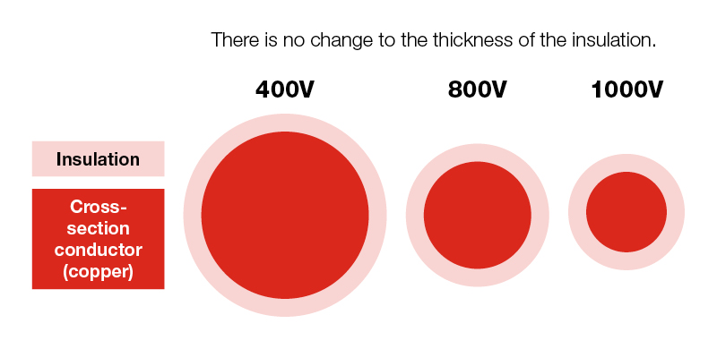
This change holds significant weight reduction potential. At 400 V, the average weight of a 150 kW copper cable sits at 1.27 kg/m (0.853 lb./ft); At 800 V, the weight almost halves to 0.673 kg/m (0.452 lb./ft). And the positive effects of lower current requirements for identical performance are not limited to charging and supply lines either. The smaller cable cross-section also allows the windings in the motors to be designed more compactly, which reduces the size of the motors. According to a German OEM, the overall weight of the vehicle has been reduced by doubling the voltage. Naturally, material costs are also reduced to the same extent.
HIGHER VOLTAGE LEVELS LEAD TO HIGHER COSTS
Although material costs are reduced, the higher voltage level raises costs elsewhere. First, 400 V architecture is the dominant voltage level in the industry right now – which means that components optimized for 400 V are produced in larger quantities and by more suppliers than the respective 800 V components – and are therefore cheaper. Also, the existing charging infrastructure right now is dimensioned with 400 V in mind, while 800 V charging stations are few and far between. So, until 800 V charging infrastructure is established on the road, some systems must be installed in duplicate in HV battery-powered vehicles. For example, an additional DC/DC converter may be needed to convert the 400 V from the charging station to the 800 V in the vehicle.
Meanwhile, 800 V also place higher demands on certain devices. For example, the inverter within the powertrain must be able to switch higher voltages, and the conversion to low voltages during start-up (900 V to 30-40 V) is also more complex – a process necessary to check the function of all electrical devices before starting.
Longer discharge time of the electric car at higher voltage levels
Due to the higher voltage levels, a lot more energy is stored in the EV’s intermediate systems, such as its cable network. The amount of energy increases as the square of the voltage. For example, in a system in which an amount of energy of 120 J remains at 400 V, 480 J remain at 800 V and even 750 J at 1000 V. This poses a challenge for the legally required rapid discharging ability of the vehicle system.
The legal requirements state that in the case of an emergency shutdown of the vehicle (e.g., after a crash), all parts of the vehicle must free of any electric potential (higher than 60 V, at least) after 5 seconds. In the case of the “conventional” 400 V, a single electric discharge unit suffices to remove any residual potential (e.g., an electric drive unit).
At higher voltage levels however, residual potential is higher – and more EDUs are needed to completely discharge all components within 5 seconds. Current trends indicate a shift towards self-discharging components, a technically feasible, albeit quite expensive solution to this problem. Additionally, costs are also increased by the more complex battery management system (BMS) which is needed at higher voltage levels due to more battery cells connected serially.
TECHNICAL CHALLENGES CAUSED BY HIGHER VOLTAGE LEVELS
Inverters, which are needed for an EV’s motor control, also face higher efforts at higher voltage levels. The electronic circuits (usually silicon IGBTs are used) within the inverter may reach their limits when voltage peaks occur; Switching to a different material such as silicon carbide (SiC) is required to ensure the required high switching power.
The switching losses depend linearly on the voltage, current, switching duration, and switching frequency. With constant power, higher voltage and lower current, the power loss can be mitigated by using fast-switching SiC-IGBTs. Another (expensive) solution could be simply switching the inverter architecture. Whether the higher efficiency are worth the higher costs should be coordinated with the OEM in both cases.
One problem that remains is electromagnetic interference (EMI) within the inverter occurs more frequently at higher voltage levels. EMIs may cause malfunctioning of the EV’s electronic assemblies, but they may also damage the insulations of the motor windings, which shortens the engine’s lifetime. They can be prevented from spreading along the cables and lines by installing improved filter units. Meanwhile, a shielded HV on-board power supply protects surrounding assemblies form EMI.
HIGHER VOLTAGE LEVELS DO NOT SOLVE ALL CHALLENGES WITH EVs
In conclusion: Switching to a voltage level higher than 400 V is by no means a perfect one-size-fits-all solution to increase efficiency, performance, and fast charging capacities of EVs. HV batteries definitely lead to large improvements in all regards, but only do so alongside a notable increase in costs. Whether switching 800 V or higher provides a competitive advantage or not must be gauged for each vehicle project individually.
Overall, higher voltages synergize best with high-performance BEVs sporting very large batteries. Here, the much higher charging power potential is much more relevant – and end customers can be expected to pay more for the improved technology. EVs of smaller sizes on the other hand benefit more from 400 V, as the lower voltage level is not only cheaper, but also provides several additional advantages.
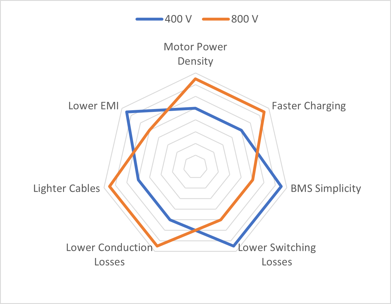
Advantages and disadvantages of 400 V and 800 V powertrain systems: HV disadvantages can be fixed with technical improvements, although higher costs should be expected.
AN EXPERIENCED HV BATTERY DEVELOPMENT PARTNER WILL BENEFIT THE EV PROJECT
Designing and developing new EVs may often come with expensive mistakes. To avoid those from the get-go, cooperating with a competent and experienced development partner such as Magna is always advantageous – for both established OEMs as well as for new start-ups entering the EV market. Years of experience with electric mobility and a diverse range of EV projects and customers have fostered Magna’s broad knowledge in dealing with the respective wishes and requirements of its clients in a timely, flexible, and project-specific manner. For example, Magna can offer flexible solutions and system variants to OEM customers and manage the integration of many diverse components from suppliers all around the world.
BATTERY DEVELOPMENT FOR HIGH VOLTAGE BATTERY ELECTRIC VEHICLES - A SUPERCHARGED SUBJECT
High voltage batteries are not only the largest and most expensive module of any battery electric vehicle, but they also hold a key function for almost any expected feature in a BEV, from performance to security. The final battery is much more than just a case into which the cells are stacked to save as much space as possible, but an integral element of the vehicle’s architecture.
Integrating the high voltage battery development into the complete vehicle system of a BEV is one of the most important tasks of any vehicle project. And the development of new battery electric vehicles currently accounts for the vast majority of projects carried out by development specialists in close cooperation with OEMs.
TARGET CONFLICTS IN HIGH VOLTAGE BATTERIES - SETTING TARGETS DEPENDING ON THE VEHICLE TYPE
Considering the many requirements of a finished battery pack, it is impossible to isolate only one as the most important. That is why main requirements need to be defined in the earliest stages of any vehicle project and in cooperation between the development partner and OEM, depending on the use case of the vehicle through Vehicle Target Setting (VTS). These main requirements may vary since a limousine prioritizing driving range and energy efficiency has different key development aspects than a multifunctional SUV, a compact car for urban settings, or an all-terrain vehicle. Development specialist Magna works with a set of 40 main Key Performance Indexes (KPI) – a number which by itself indicates the variety of requirements within high voltage battery development.
Part of this process is solving target conflicts. Maximum energy density (as much stored energy in as little space as possible) can conflict with indispensable security requirements, a boost charge feature can weigh down on the battery’s life span, etc. A vehicle’s driving range is not solely influenced by battery capacity, but also by how efficiently the complete vehicle uses the provided energy. A rather large but heavy and expensive battery will not provide more driving range when used inefficiently than a smaller, but efficiently used battery. Additionally, boost charging will only make sense in combination with optimized battery, charging, and thermal management – or else the battery cells’ aging is accelerated.
Depending on the vehicle’s concept, optimizing driving range must also be balanced against protection against external impacts since electric all-terrain vehicles could be damaged from underneath when travelling off-road. This is not only achieved by strengthening the vehicle’s chassis, but also by providing enough free space to avoid damage by indentations to battery cells, conditioning, and sealing systems. However, these measures reduce possible packing density of cells and thus volumetric energy density.
A HOT TOPIC - THERMAL SECURTY OF HIGH VOLTAGE BATTERIES
The thermal security of high voltage batteries will always be an important issue – especially for the general acceptance of battery electric vehicles. Therefore, preventing incidents relevant to the battery pack’s security by implementing suitable measures is a central aspect of battery development.
On the cell level, thermal runaways are particularly important to watch out for. A thermal runaway occurs when electrochemical processes inside the battery get out of control due to overheating, thus creating more heat and further thermal runaways.
On the pack level, one thermal runaway can ‘infect’ other battery cells and start a chain reaction called thermal propagation.
Occasionally, news and videos of burning battery electric vehicles that cannot be extinguished will circulate traditional and social media. Stories like these regretfully nurture the myth that BEVs and their battery packs are easily ignitable. However, this statement cannot hold its ground on an empirical level. Studies show that the probability of a battery electric vehicle catching fire only corresponds to a fraction of the fire risk of an ordinary combustion engine vehicle (ICE).
According to a study from the Jülich Research Center of the Helmholtz-Institut in Muenster, only two fire incidents on average occurred per billion driven kilometers in battery electric vehicles. On the contrary, about 90 fire incidents on average occurred per billion driven kilometers in combustion engine vehicles. Of course, this data is based on relatively new technology, so the first vehicles produced on a larger scale have not yet exceeded a ten-year lifespan. Nonetheless, the numbers clearly show that the security of battery electric vehicles is on par with combustion engine vehicles when it comes to both ignition risk and fire load, i.e. the mass of combustible material.
Ignition risk in BEV and ICE
However, how a fire progresses is utterly different in these vehicle types. An ICE burns out quite quickly as soon as the carried fuel ignites. In contrast, a BEV burns out slowly, sometimes even over the course of several hours since thermal runaways slowly spread from cell to cell instead of the entire fuel supply combusting at once. This delayed reaction might seem more treacherous, but it is actually safer for the passengers. Even when the thermal runaway of a battery cell has already started, there is more than enough time for the passengers to safely evacuate the vehicle. That is why a UNECE legal standard dictates that at least five minutes must pass from the first detection of a thermal incident and the possible endangerment of passengers. Today, this standard has already been outperformed as recent designs strive to eliminate the possibility of a thermal propagation event altogether.
A variety of possible causes – thermal incidents in high voltage batteries
Surprisingly, the internal short circuit of cells is only seldom the cause for a thermal runaway, and in extreme scenarios, a thermal propagation. In most instances, the self-induced runaway of a battery pack usually happens because of quality deficits during the production process of the battery cells, especially through the contamination of the cell’s inner chemistry. However, production processes today are much more refined than in the past, and that is why internal runaways are not supposed to happen without outside influence anymore.
However, various other factors that might lead to a cell’s runaway can be prevented by appropriate countermeasures. For example, an infringement of operation strategy of either the cell or the cell’s chemistry due to temperature, charging or discharging performance. Under such subpar circumstances, dendrites can form – twig-like structures inside the cell that can permeate separators and cause internal short circuits afterwards.
Mechanical damage is another significant risk that needs to be prevented in the development and integration of high voltage batteries into the vehicle. This type of damage can occur through the short-term effect of extreme forces. For example, during a massive accident with extensive destruction, or through slow deformation from outside, like when a foreign object indents or perforates the chassis during off-road usage of the car. Fires caused by other vehicle components can also heat the battery from the outside, leading to a thermal incident. Examples are flashovers from low voltage electrical systems or the combustible cooling agent in the air condition. There is also the possibility of short circuits outside the battery pack that heat the high voltage paths, e.g. from the engines, the onboard-chargers, or DC/DC-converters. Finally, longer periods of strenuous use might also lead leaks in the battery enclosure, allowing moisture and dirt to intrude into the battery, which in turn might lead to electrical conduction and a short circuit inside the battery pack.
DIVIDING THE LOAD - HIGH VOLTAGE BATTRY AS AN INTEGRAL COMPONENT OF THE CHASSIS
Although all these potential dangers are improbable, they still need to be seriously considered during the basic conceptual design of the vehicle and the battery development phase. For that reason, the robustness of the battery against outside influences is tested thoroughly. Development expert Magna usually tests extreme load cases via simulation, as well as during the entire design verification process (DVP). The high voltage battery must endure these tests without sustaining serious damage like deformations on the cellular level, leaks, or loss of functionality. Battery development and vehicle design must work closely together since the high voltage battery pack contributes heavily to the structural performance overall. That is because the body shell, underbody, and battery case divide the load transmission – in normal operation as well as in case of an accident.
IN THE BEGINNING THERE WAS THE CELL - PARALLEL DEVELOPMENT OF BATTERY AND CELL
Development of the battery cells usually starts long before the actual development of the vehicle itself – even if the battery cell supplier has already been chosen at the beginning of the battery development. This is particularly common in projects with larger OEMs that already have a steady business relationship with cell manufacturers or have set foot into cell production themselves. If not, a suitable cell manufacturer needs to be chosen according to the specific requirements of the project. The overall battery development is neither accelerated nor slowed by this process since the development of battery and cells proceed parallel to each other.
To choose a suitable cell manufacturer, multiple basic concepts are developed by adaptation from the vehicle’s requirements first. Different cell and cell module manufacturers can then be easily compared and assessed from a technical perspective for the respective project. After evaluating other criteria like cost, quality, and production capacity, a recommendation for an eligible business partner can be provided. However, there is a stable trend across all cell suppliers towards continuously improving the cells’ chemistry regarding capacity, aging, security, and cost factor. Cell integration also takes further strides in development, and the general energy density of high voltage batteries is increasing by 10 to 15 percent each year.
The higher the integration degree, the higher the challenge
A few years ago, batteries were mostly created by using the module-to-pack method, i.e. by combining multiple cell modules into a battery pack. Nowadays, there has been a change towards the cell-to-pack method by integrating large arrays of combined cell formations into a battery pack. However, there is already a new approach on the horizon which integrates the cells directly into the chassis of the vehicle. This way, the cells’ packing density as well as their gravimetric and volumetric energy density can be further improved. But with the ever-increasing compactness of cell integration come technical difficulties regarding the prevention of thermal propagation. In the future of this development, new materials need to be introduced that can stop, or at least decelerate, the spread of heat from one battery cell to another.
The most important countermeasure against the overheating of a runaway cell is the dissipation of excess heat before it can infect another cell. In addition, increasing pressure created by the heating process needs to be safely released in a controlled fashion before the cells can burst open. That is why safety vents inside the casing are required. Additional pipes within the casing design can also help to divert hot gases over 500°C so that the heat cannot transfer to other battery cells. Moreover, a type of cell which can switch itself off if electrochemical processes reach critical temperatures is currently in development.
Creating a battery electric vehicle that is safe under even extreme circumstances is only possible if measures for the battery cell, the battery pack, and the complete vehicle work together. That is why having battery development and vehicle development under one roof can bring great benefits since they need to work hand in hand with each other to guarantee the best possible outcome.
REGULATIONS AND RULES - SLOW AND STEADY MAKES THE LAW
Of course, there are different legal regulations in place for high voltage batteries in BEVs depending on the location of the respective market, but they are always subject to steady change. However, it is almost impossible for battery developers to just consider regulations that are effective at the start of any given project since battery development is quite time-consuming. Depending on available resources – like how far the vehicle concept design has come, and in which state of maturity the battery cells are –battery development takes around three to four years. During this time frame, legal regulations usually change or are about to change.
Thus, vehicle developers need to be acutely informed about regulations that are currently in place, planned for the future, under development, or available as a draft at the moment. But years can pass until those early drafts become legally binding. On one hand, because there are always attempts to find and solidify global standards. On the other hand, committees for standardization work steadily, but slowly. Nonetheless, even trying to fulfill future regulations might be an insufficient effort to stay ahead of legal changes. That is why a competent battery developer will always strive to outperform current and even future requirements since an OEM’s vehicle project will stay in production for a long period of time and must keep conforming to regulations all the while.
EXTENSIVE EXPERIENCE IN ALL AREAS OF DEVELOPMENT REAPS THE MOST BENEFITS
There are quite a few inexperienced battery developers that pop up more spontaneously on the market and present concepts that seem attractive at first glance. However, a closer look usually reveals that these concepts cannot be applied to reality. Oftentimes, the battery is only developed in isolation and the requirements of the complete are not thoroughly considered. Working with an experienced development partner can prevent many problems down the line and reap a lot of benefits. Magna offers extensive competence in all areas of vehicle development and can provide the best solutions for high voltage battery development without time-consuming and costly errors.
TO SUMMARIZE: SUCCESSFUL EV PROJECTS REQUIRE MANY DEVELOPMENT COMPETENCIES IN MAY DIFFERENT AREAS
Developing EVs presents both established automotive manufacturers and new entrants with many new challenges. The host of novel vehicle brands that are emerging during the global shift in mobility may give the impression that BEV development is a simple matter that even completely inexperienced industry newcomers can handle. However, the reality is that it is a mountainous undertaking to release a new EV model, let alone an entire EV model series, onto the road – and subsequently convince end customers of its validity on the market. An experienced and competent complete vehicle development partner supports established OEMs and new entrants alike in implementing new e-car projects faster, better, and ultimately more cost-efficiently.
How can we support you in developing your own electric vehicle? Contact us at discovermore.magnasteyr@magna.com
Or visit magna.com/stories/inside-automotive for more insights into automotive development and production.
Stay connected with Inside Automotive!

We want to hear from you
Send us your questions, thoughts and inquiries or engage in the conversation on social media.
Related Stories

Project Management as the Key to an Optimized Development Phase and a Stable Start of Production (SOP)
Inside Automotive

The Future of UI/UX Concept Visualization in the Automotive Industry: Innovations, Challenges, and Perspectives
Inside Automotive
Stay connected
You can stay connected with Magna News and Stories through email alerts sent to your inbox in real time.